Number Systems and Binary Concepts
When I was a child, I remember my grandmother once confessing that she had no idea how a television actually worked. It was a mysterious box for her: she pressed a button, and pictures appeared. At the time, I did not understand it either.
For many of you reading this book, the low-level aspects of MIDI communication may feel similar. MIDI messages are sent, notes play, sounds change, devices respond - but what is actually happening underneath?
In many situations, that deeper knowledge is not strictly necessary. If you are simply using a DAW or a sequencer to record and play back MIDI, everything works without you ever thinking about bits and bytes. However, once you move into more advanced topics, such as working with SysEx messages, handling signed (negative) modulation values, or troubleshooting complex setups, that underlying understanding becomes highly relevant.
This chapter is here to gently lift the curtain.
My goal is to give you just enough insight into how MIDI works internally so that you can use it efficiently on your Electra One, no more and no less. We will focus only on what is truly necessary for the rest of this book. There is no need to become a computer engineer. You simply need to understand the fundamental building blocks.
If this chapter feels a little dense at first, that is perfectly normal. You may choose to skim it and return later. However, I strongly recommend coming back as soon as you begin encountering terms such as bit, byte, binary, hexadecimal, LSB, or MSB and feel unsure about their meaning.
Once these concepts click into place, everything that follows will make much more sense.
What is happening in the Midi cable?
Imagine a master keyboard sitting on a stand and a rack module mounted in a rack. A MIDI cable runs between them.
In the previous chapter, we learned that the keyboard typically sends MIDI messages to the rack module. The keyboard acts as the transmitting device, while the rack module receives those messages and responds to them by playing the notes. We also learned that both devices must be configured to use the same MIDI channel in order to exchange channel (voice) messages. In addition, they may exchange various system messages.
But what does it actually mean to send a message? What physically happens inside the cable when a key is pressed?
You probably know that I am going to say it's about electric signals. Yes, it is. The MIDI cable acts as a pipe to deliver the MIDI messages, in the form of electric pulses, from the MIDI Out connector of the sender to the MIDI In connector of the receiving device.
A good, yet rather simplified, analogy is to imagine that these pulses are like Morse code signals. Certain combinations represent letters, and the letters are used to compose words, and the words carry the meaning and the instructions.
It is an analogy; computer systems do not use Morse code, letters, and words to transmit their commands, at least not in low-level communication. They use bits, bytes, and protocols.
If the term computer system sounds strange while talking about the master keyboard and the rack module, well, believe me, if there is a MIDI connector on your device, there is also a computer in it, no matter how analog it might be.
In Morse code we use elements; there are either dots (actually called dits, short beeps) or dashes (called dahs, long beeps). Various combinations of dits and dahs represent letters, and we use pauses between them to make sure that the dits and dahs of the individual letters do not get mixed up.
In a computer communication system such as MIDI, the elements are the bits. They are the individual pulses flowing through the wire in the cable from the sender to the receiver. If the pulse is present at a given time, it represents a value of 1. If the pulse is not present at a given time, it represents 0. So we can say that there is a flow of 1s and 0s between the MIDI device that sends the MIDI messages and the device that receives them.
Each group of 8 bits forms a byte. A byte may look like this: 00110101.
It is a series of received pulses and gaps between them converted into 0s and 1s according to the rule described above. You can think of a byte as being similar to a letter in Morse code, a basic unit that carries meaning.

An important difference here is that a byte represents a number between 0 and 255. If you wonder why 255, it is because that is the total number of different values you can represent with all possible combinations of eight bits (0s and 1s). You will learn how to convert bits to numbers and numbers back to bits later in this chapter.
MIDI Protocol
A protocol is essentially an agreement.
In everyday life, we use protocols all the time. When two people speak the same language, they follow shared rules of grammar and vocabulary. Those rules allow one person to transfer meaning to another, whether they are expressing ideas, asking questions, giving instructions, or making requests.
Human language, however, is full of ambiguity. The person listening may interpret our words slightly, or completely, differently from what we intended. Context, tone, and personal experience all influence understanding.
Computer systems, on the other hand, must follow much stricter rules. Ambiguity would lead to errors and misinterpretations. When two computers communicate over the internet, they rely on precise technical agreements. Every bit of data must be structured and interpreted exactly as defined. Without those strict rules, communication would simply fail.
The same concept applies to MIDI communication. The MIDI protocol is an agreement that defines what the bits and bytes transmitted over the MIDI cable mean and how they should be interpreted. After all, bits and bytes by themselves do not carry meaning.
To give them meaning, MIDI devices must agree on three fundamental things:
- how fast the data is sent
- how the data is structured
- what the data actually means
The term data simply means collections of bits and bytes here. These three rules form the agreement - the protocol.
Let's look at a simplified example.
If a synthesizer receives the following sequence of three bytes:
10010010 00111100 01111111
it will interpret this sequence according to the MIDI protocol and respond by playing a note, specifically, note number 60 (Middle C) at maximum velocity on MIDI channel 3.
Why does it do that?
Because the protocol defines exactly how those bits are organized and how they should be understood.
The rest of this chapter is about explaining why that particular sequence of bits produces that specific result.
To understand it fully, we need to take yet another short detour into number systems. Understanding number systems is especially important when working with SysEx messages, where binary and hexadecimal representations are used frequently.
Number systems
We humans use the decimal system, also called base-10. The reason is unsurprisingly simple: most of us have ten fingers.
Long before calculators and computers existed, people counted using their hands. Over time, this natural habit became a standardized way of representing numbers. In the decimal system, each digit in the number can have ten possible values: 0 through 9. If I go back to our Morse code analogy, each element can be a value between 0 and 9, instead of dit or dah.
It feels natural to us because we have used it our entire lives.
Contemporary computers, however, do not have fingers. Inside a computer, or inside a MIDI device, information is represented using electrical signals, the pulses we mentioned earlier. At the lowest level, a digital electronic circuit can usually exist in only one of two states:
- on (voltage present)
- off (voltage absent)
Because there are only two possible states, computers use the binary system, also known as base-2. In binary, each digit - called a bit - can have only two possible values: 0 or 1. The value 0 represents the off state, where no voltage is present. The value 1 represents the on state, where voltage is present.
Every number, every MIDI message, and every piece of digital information is ultimately built from long sequences of these zeros and ones.
Binary is not more complicated than decimal. It is simply better suited to the way electronic circuits operate. The only difference is that binary is limited to two digits: 0 and 1 instead of the ten digits (0 through 9) we use in the decimal system.
Now we face a practical problem. Binary numbers can become very long and difficult for humans to read. The chances that you will mistype our previous example of the MIDI message are fairly high. It is simply too many 0s and 1s:
10010010 00111100 01111111
To make binary data easier to read and write, engineers often use the hexadecimal system, also called base-16. In hexadecimal, each digit represents four binary bits. This allows long binary sequences to be written in a much shorter and more manageable form.
For example:
00111110 → 3E
10000000 → 80
At first glance, your brain may refuse to accept 3E as a number. That is perfectly normal reaction. To understand it, we need to revisit how digits are defined in the number systems we have just discussed.
Binary uses only the digits 0 and 1, because there are only two electrical states: on and off. The decimal system uses digits 0, 1, 2, 3, 4, 5, 6, 7, 8, 9, because humans have ten fingers. Hexadecimal uses digits 0, 1, 2, 3, 4, 5, 6, 7, 8, 9, A, B, C, D, E, F, because programmers have sixteen fingers.
This allows single hexadecimal digit to represent sixteen different values. The letters A through F simply stand for decimal values 10 through 15.
Hexadecimal is not here because computers need it. Computers still operate in binary. Hexadecimal is used because it is more practical for us humans. It acts as a bridge between the binary world of machines and the decimal world we are used to.
You may wonder: why do we need that bridge at all? Why not use only binary and decimal?
I believe there are two practical reasons for that:
First, converting a binary number to hexadecimal is extremely simple, because each hexadecimal digit corresponds exactly to four binary bits. The conversion can be done by grouping the bits in sets of four.
Second, hexadecimal numbers are easier for us to reason about intuitively. For example, we can immediately see that 3E is smaller than 80, and that it is roughly half of 80. The same numbers expressed in binary: 00111110 and 10000000, feel far less intuitive.
Hexadecimal gives us compact notation without losing the structure of the underlying binary data. And that is exactly why it is so widely used in MIDI documentation, debugging tools, and SysEx messages.
Now let's take a closer look at the more practical aspects of composing, decoding, and converting numbers between different number systems.
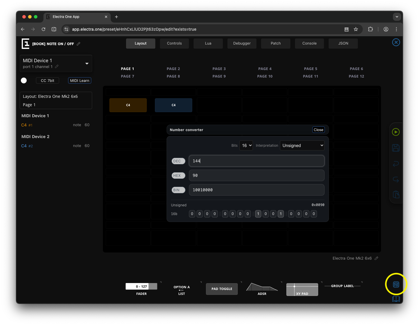
This is the part that can feel a little tedious. Working with bits and number conversions is not always the most exciting topic, especially in a book about music. Fortunately, you do not have to perform these conversions manually every time. The Electra One web editor includes a built-in Number Converter that makes working with binary, decimal, and hexadecimal values much easier. You can open it from anywhere in the editor by clicking the icon in the toolbar on the right side.
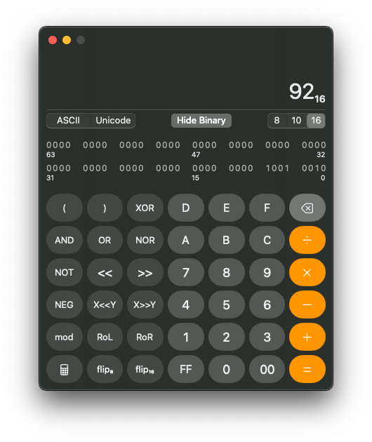
If you are using macOS, the Calculator application also provides a programmer mode that allows you to convert between number systems and perform calculations at the same time.
Decimal Number System
The decimal system, other times referred to as base-10, is the one humans use every day. It uses digits: 0 – 9 Each position in the number represents a power of 10
Example:
345 = 3×100 + 4×10 + 5×1or
1024 = 1×1000 + 0×100 + 2×10 + 4×1Decimal is convenient for humans, but inefficient for electronic systems.
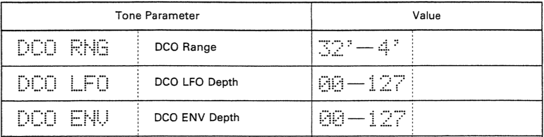
In MIDI documentation, decimal numbers are written the way we are familiar with from everyday life: 0, 12, 345, 1024. Decimal notation typically appears when displaying value ranges, discrete values, or commonly referenced parameters such as velocity, number of semitones, and similar quantities.
For the sake of simplicity, we will focus only on whole numbers here and leave fractions aside.
Binary Number System
Binary, akabBase-2, is used by computers and digital communication protocols. The binary has only two digits:
- 0 (off)
- 1 (on)
Each position represents a power of 2.
Example:
1011 (binary)
= 1×8 + 0×4 + 1×2 + 1×1
= 11 (decimal)
or
101011001 (binary)
= 1×256 + 0×128 + 1×64 + 0×32 + 1×16 + 1×8 + 0×4 + 0×2 + 1×1
= 345 (decimal)
or
10000000000 (binary)
= 1×1024 + 0×512 + 0×256 + 0×128 + 0×64 + 0×32 + 0×16 + 0×8 + 0×4 + 0×2 + 0×1
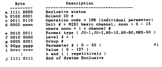
= 1024 (decimal)Binary maps directly to signal levels in electronic circuits. In MIDI documentation you will often find binary numbers in the sections that descibe MIDI messages, especially the SysEx data exchange.
Bits and Bytes
A Bit a single binary digit (0 or 1). A Byte is 8 bits grouped together.
Example byte:
01100001An 8-bit byte can represent numeric values from 0 to 255. In other words, a byte can encode 256 distinct values (2⁸ = 256). In MIDI, you will often encounter 7-bit and 14-bit data values. This means that the numeric value does not always use the full 8-bit range. The explanation why will follow later.
Wxample of the 7-bit value:
0100001Wxample of the 14-bit value:
11100100100001Unlike an 8-bit number, which can represent 256 distinct values, a 7-bit number can represent only 128 values (2⁷ = 128). A 14-bit number provides a much wider range of 16,384 values (2¹⁴ = 16,384).
As you can see, the 14-bit example is already becoming difficult to read. If I asked you whether the bit in position six is a 0 or a 1, you would probably need a moment to count carefully. To make binary numbers easier to read, it is common practice to insert spaces as visual separators. Most often, bits are grouped into blocks of four. These groups of four bits are called nibbles.
The same 14-bit value written with nibble grouping might look like this:
0011 1001 0010 0001The spaces do not change the value of the number. They simply help our eyes recognize patterns and individual bits more easily.
Binary numbers are usually written as sequences of digits and are often padded with leading zeros to match a specific bit width (7-bit, 8-bit, 14-bit, 16-bit, and so on). Again, the leading zeros do not change the value; they only define the intended size of the data.
Sometimes binary numbers are also marked explicitly using prefixes or suffixes, such as:
0010001
001 0001
0001 0001
0b00010001
00010001b
All these examples are the same binary number.
Hexadecimal Number System
Hexadecimal, often simply called hex or base-16, is a compact way of writing binary numbers. It uses the following digits:
0, 1, 2, 3, 4, 5, 6, 7, 8, 9, A, B, C, D, E, FWhere:
A = 10
B = 11
C = 12
D = 13
E = 14
F = 15
Each hexadecimal digit represents 4 binary bits, also known as a nibble. A nibble, being a 4-bit number, can express exactly 16 distinct values. This matches perfectly with the sixteen symbols used in hexadecimal notation.
The following lookup table translates binary nibbles into their decimal and hexadecimal equivalents:
| Decimal | Hex | Binary |
|---|---|---|
| 0 | 0 | 0000 |
| 1 | 1 | 0001 |
| 2 | 2 | 0010 |
| 3 | 3 | 0011 |
| 4 | 4 | 0100 |
| 5 | 5 | 0101 |
| 6 | 6 | 0110 |
| 7 | 7 | 0111 |
| 8 | 8 | 1000 |
| 9 | 9 | 1001 |
| 10 | A | 1010 |
| 11 | B | 1011 |
| 12 | C | 1100 |
| 13 | D | 1101 |
| 14 | E | 1110 |
| 15 | F | 1111 |
You could, of course, use powers of 16 to perform the conversion mathematically. In practice, however, the lookup table is far more convenient. After years of working with MIDI, I can convert nibbles almost automatically, employing the spinal cord only, leaving the brain free for more interesting tasks. I am sure you will reach that point soon too.
Using the lookup table you can easily translate the binary to hexadecimal like this:
Binary:                       10101100
Split to nibbles:             1010 1100
Nibbles as decinals values:   10   12
Nibbles as hex values:        A    C
So:
10101100 (binary) = AC (hex)As you can see, converting between binary and hexadecimal is straightforward once you remember that every 4 bits equal one hex digit. This direct relationship is the reason hexadecimal is so widely used in MIDI documentation and debugging tools.
Hexadecimal numbers are often written with leading zeros to match a specific byte width. Different notations are used to distinguish hexadecimal from decimal numbers:
In MIDI documentation, a suffix h is used (for example, 7Fh). In programming, a prefix 0x is commonly used (for example, 0x7F). From now on, we will use the 0x prefix. This is the format required by the Lua programming language, which we will use later in this book.
So, the example mentioned above, using the 0x notation:
10101100 (binary) = 0xACMost Significant Bit (msb) and Least Significant Bit (lsb)
In any binary number:
- the
msb(most significant bit) is the leftmost bit - the
lsb(least significant bit) is the rightmost bit
The term significant refers to how much influence a bit has on the numeric value.
The msb contributes the largest possible value in that binary number. If you change the msb from 0 to 1, the number increases by the largest step possible within that bit width. In an 8-bit number (a byte), the msb represents the value 2⁷ = 128:
1000 1101
↑
Here, the msb contributes 128 to the total value.
On the other hand, the lsb contributes the smallest possible value. It represents 2⁰ = 1
1000 1101
        ↑
Changing the lsb from 0 to 1 increases the number by only 1.
So, every binary number always has both:
Binary:   10110010
          ↑      ↑
         msb    lsb
The msb defines the largest step in the number. The lsb defines the smallest step.
Understanding this idea is important, because MIDI uses the msb of a byte in a special way to distinguish between different types of data. We will see how that works in the next section.
Why MIDI Uses 7-bit and 14-bit Values
Technically, the MIDI protocol uses 8-bit bytes to transfer message data between MIDI devices. These days, there is probably no human being who has not heard of an 8-bit game console, 16-bit data bus, 32-bit processor, or 64-bit computer. Numbers like 8, 16, 32, 64, and their more everyday companions such as 128MB, 256MB, or 4GB, have simply become part of our lives. Of course, these obscure numbers stem from the nature of the binary number system and the power of love - sorry, the powers of two.
And then, in the world of MIDI, you immediately run into something like 7-bit values with their maximum set at 127. And you wonder: why?
The MIDI protocol uses the msb (most significant bit) of every 8-bit byte to distinguish between two types of bytes:
- a Status byte, which defines the type of MIDI message
- a Data byte, which carries the message data (such as note number, velocity, or control change value)
When the msb is set to 1 (meaning the byte value is 128 or greater), the byte represents a Status byte. When the msb is set to 0 (meaning the byte value is between 0 and 127), the byte represents a Data byte.
Because the msb of a data byte must always be 0, only the remaining 7 bits are available to carry the actual numeric value.
This effectively limits standard MIDI data values to the range:
00000000 – 01111111resulting in
0 - 127 (dec)For higher-resolution messages, such as Pitch Bend, a single 7-bit value is not sufficient. In those cases, MIDI combines two 7-bit data bytes, resulting in a 14-bit value. A 14-bit number can represent values from 0 to 16383 (2¹⁴ = 16,384 distinct values).
This design based on the Status bytes and Data bytes is actually one of the hidden gems of the MIDI protocol. It makes MIDI a self-synchronizing protocol. This means the receiving device can always determine where a new message begins simply by checking the first bit of each byte:
- If the
msbis 1 → this byte starts a new MIDI message. - If the
msbis 0 → this byte belongs to the current message as data.
This simple rule allows MIDI devices to recover from transmission errors or dropped bytes. Even if some data is lost, the receiver can resynchronize itself as soon as the next status byte appears.
If your patience is starting to reach its limits, there is good news: we are getting close to the end of this chapter.
Signed vs Unsigned Numbers
The very last topic we will touch on in this chapter is how negative values are represented in MIDI.
Some things in life can only be positive, like the amount of time you spend with your Electra One. It is either zero or some positive duration. Other quantities, however, can go below zero. Outside temperature is a classic example. It can be positive, or it can drop below zero when it is freezing. That was my metric/SI brain speaking.
Based on what we have discussed so far, it might seem that bytes can carry only positive values. And in a way, that is true. A binary number is constructed by summing powers of two, and powers of two are always positive. There is no obvious way to create a negative number by simply adding together positive values.
Still, clever engineers of the early computing era came up with practical solutions. If you work with MIDI long enough, you will encounter them sooner or later.
Unsigned Numbers
There is not much else to add to what we said so far, Unsigned numbers represent only non-negative values.
For example 8-bit unsigned byte will exactly cover range of 256 numeric values starting with 0 and going up to 255.
The unsigned numeric values are used for:
- MIDI notes
- velocities
- aftertouch pressure
In these cases, negative values simply do not make any sense.
Signed Numbers
Signed numbers represent both positive and negative values. This becomes necessary whenever a value can move in two directions, such as:
- Pitch bend direction (up or down)
- Offsets
- Relative movements
To represent signed numbers in binary, we need a way to indicate whether a value is positive or negative. In technical terms, we must encode that information within the structure of the bits inside a byte.
There are several ways to do this. One of the simplest approaches is called offset (or biased) representation.
Zero Offset
In offset representation, a specific positive numeric value is treated as zero. Values above it are interpreted as positive, and values below it are interpreted as negative.
For example, consider a 7-bit MIDI value in the range 0 to 127. If we choose 63 as the center (zero point), we can interpret the value by using the following formula:
signed_value = raw_value − 63This means:
- Values greater than 63 become positive
- Values less than 63 become negative
- 63 itself represents exactly 0
So:
63  →  0
64  → +1
62  → -1
127 → +64
0   → -63
This method does not change the actual binary format. The byte still carries a standard 7-bit unsigned value. It is just the interpretation that changes.
Electra One controllers handle this kind of conversion for you automatically.
If you configure a parameter in the editor with a minimum display value below zero and a maximum value above zero, the controller will dynamically calculate the center point. The midpoint between the display minimum and maximum becomes the effective “zero” position.
In other words:
- The MIDI data range remains in the 0–127 range.
- The display and internal logic interpret the midpoint as zero.
- The signed value is calculated relative to that midpoint.
This allows you to work comfortably with signed parameters without manually performing conversions.
Offset representation is simple, practical, and very common, especially in MIDI contexts. However, computers internally often use a different systems: sign bit and two's complement, to represent signed values more efficiently for arithmetic operations. We will look at that next.
Sign Bit
Another simple way to represent signed numbers in binary is to use a sign bit.
In this approach, the msb (most significant bit) is reserved to indicate whether the value is positive or negative:
- 0 → positive
- 1 → negative
The remaining bits then represent the numeric magnitude.
For example, in a 7-bit value, the highest bit (bit 6, since we start counting from 0) would act as the sign bit:
0xxxxxx  → positive
1xxxxxx  → negative
However, this introduces an important requirement: You must always know the bit width of the data.
In other words, you must know whether you are working with a 7-bit value, an 8-bit value, a 14-bit value, and so on. Only then does it become clear which bit is the msb—and therefore which bit serves as the sign bit.
When working with MIDI documentation, this information is always provided. The specification will clearly state whether a value is 7-bit, 14-bit, or another size. Without that information, it would be impossible to correctly interpret the sign.
Electra One fully supports working with sign-bit representations. When configuring parameters in the editor, you can specify the bit width and interpretation mode, allowing the system to correctly treat the highest bit as the sign bit and handle the conversion for you. The form to enter this information will be shown as soon as you set the minimum display value below zero.
It is worth noting, however, that the simple sign-bit approach has limitations. For example, it creates two possible representations of zero (positive zero and negative zero), and arithmetic operations become more complicated.
This is why modern computing systems typically use a more refined method called twoss complement, which we will explore next.
Two’s Complement Representation
Two’s complement is the standard method used in almost all contemporary processors and digital systems.
For an 8-bit number, two's complement provides the range from -128 to 127.
Notice that the total number of possible values remains 256, exactly the same as in the unsigned 8-bit case. The difference is how those values are interpreted.
The range is symmetrical around zero (with one extra negative value). There is only one representation of zero. And arithmetic (addition and subtraction) works naturally.
Positive numbers are represented exactly the same way as in unsigned binary:
+5
Binary: 00000101
To express a negative number you need to take a few oerations"
- Write +5 in binary
- Invert all bits
- Add 1
like this:
 5  = 00000101
~5  = 11111010 (inversion operation)
+1  = 11111011
If the MIDI device or the Electra One MIDI controller knows that the two's complement notation is used, the midi value 11111011 will be treated as -5.
At first glance, the 11111011 may look like a completely unrelated number. But here is the elegant part: If you add +5 and -5 together in binary, the result becomes zero (ignoring overflow). The arithmetic simply works. That is the real strength of two's complement.
Signed numbers in MIDI
Most MIDI data values are unsigned. However, when working with higher-level logic, especially in scripting or working with SysEx processing, signed interpretations often appear.
Electra One fully supports signed value interpretations, including two's complement behavior when appropriate. When configuring parameters in the editor, you must always specify the bit width (for example, 7-bit or 14-bit). That definition determines:
- where the msb is located
- whether it acts as a sign indicator
- how the numeric range is interpreted
Without knowing the bit width, signed interpretation would be impossible.
Pitch Bend and Signed Values
Pitch Bend is a practical MIDI example of what we earlier described as zero offset (biased) representation.
Technically, Pitch Bend is transmitted as two 7-bit unsigned data bytes, forming a single 14-bit value in the range from 0 to 16383. The zero offset is set at value 8192, giving us an effective range from -8192 to +8191, with 8192 meaning no Pitch Bend is applied.
MSB and LSB in Multi-Byte Values
For values larger than 7 bits (such as 14-bit MIDI values), the data must be split into multiple 7-bit bytes.
In such cases, one byte carries the more significant portion of the value, and another carries the less significant portion.
For a 14-bit value, the structure looks like this:
14-bit value:
[ MSB (7 bits) ][ LSB (7 bits) ]
In the example above:
- MSB (Most Significant Byte) contains the higher-order bits and therefore has a greater influence on the overall numeric value. In MIDI terminology, the MSB is often considered the coarse part of the data value.
- LSB (Least Significant Byte) contains the lower-order bits and contributes the smaller increments. For that reason, MIDI treats the LSB as the fine adjustment.
One of the elegant aspects of this design is backward compatibility. MIDI devices that do not recognize, or are unable to process, the LSB part (and therefore cannot use the full 14-bit resolution) can simply read the first MSB byte. By doing so, they effectively operate at a reduced resolution of 128 distinct values.
The MSB and LSB is directly related to what we explained earlier about msb and lsb bits inside a single byte. The same principle now applies at the byte level.
Throughout the rest of this book, we will use msb and lsb when referring to individual bits and MSB and LSB when referring to bytes.
And with that, we close our excursion into the number systems used in MIDI. I hope you gained some useful insight along the way. And I will admit, I am really happy to have this chapter behind me.