

Version5.0.0 beta
The Main Menu
Overview
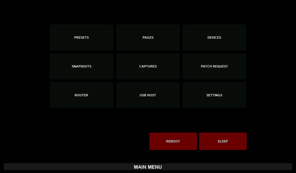
The main Menu gives you access to most of Electra One’s features and configuration options. It’s designed to keep essential functions within easy reach while leaving the hardware buttons free for actions you use more frequently.
To open the main Menu, swipe down on the right side of the touchscreen. The screen is divided into three swipe zones of equal width, and a downward swipe opens a different window in each of them:
| Swipe down on | Opens |
|---|---|
| the right third | the MAIN MENU, described in this chapter |
| the middle third | the page buttons, described in The Bottom bar |
| the left third | the PRESET MENU, described in The Preset Menu |
You may notice small dotted indicators in the Status Bar — these mark the boundaries between the three zones. To open the Menu, make sure you swipe down to the right of the rightmost indicator mark.
Once the menu is open, you can navigate using the on-screen buttons, or swipe down again to close it.
The main Menu provides access to the following features:
- Preset selection
- Page selection within the current preset
- Devices used in the current preset
- Snapshots associated with the current preset
- Captures (recorded MIDI data) for the current preset
- Patch request from a connected MIDI device
- Router configuration
- USB Host management
- Controller settings
- Reboot the controller
- Sleep mode (standby)
Preset selection
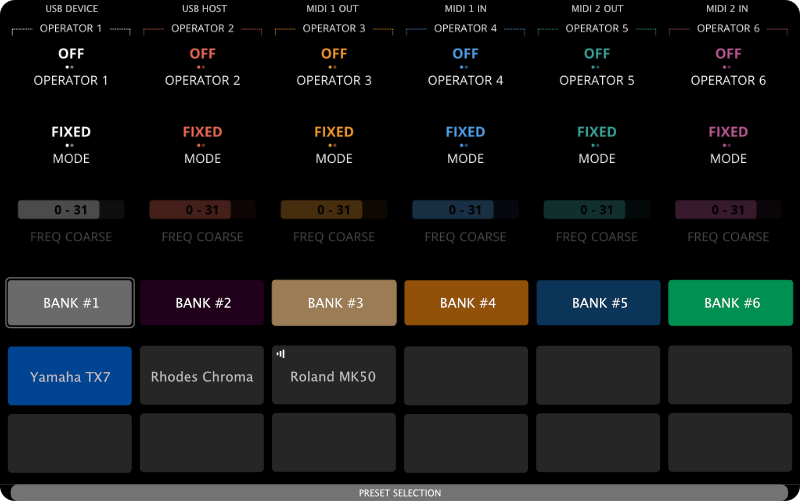
There can be up to 72 presets stored in the Electra One controller. They are organized in six banks of twelve presets.
Changing presets
Once you’re on the Preset Selection screen, simply tap the preset you want to load. Alternatively, you can activate it by touching the corresponding knob.
Note: The knob touch feature can be disabled in the controller’s settings if preferred.
The highlighted preset (shown in blue) is the active one — it’s the preset you’re currently working with, and the one sending and responding to MIDI data.
Electra One also supports multiple active presets using a feature called preset pinning. When you pin a preset, it continues to run their Lua and process MIDI even after you switch to another preset. This is useful when you want to keep background controls or automation running from another preset.
Pinned presets are marked with a pin icon in the upper-right corner of their button. A separate mark in the upper-left corner shows that a preset is running. Both marks can be shown at once: a pinned preset is running by definition, and the preset you are working with is running without being pinned. We’ll cover how to pin and manage presets in more detail later in this guide.
It’s also important to understand how loading works. A preset is physically loaded and initialized the first time you use it after powering on the controller. Once loaded, switching back and forth between presets does not reinitialize them — they retain their previous state. However, unselected (but previously loaded) presets remain inactive: they do not process MIDI or run Lua scripts unless they are pinned.
Changing banks
You can switch between preset banks by tapping the on-screen bank buttons:

Each bank can hold up to twelve presets. Once you select a bank, you can choose a preset from that bank using the method described above.
The active bank is indicated by a thin outline around its button:
The labels and colors of the bank buttons can be customized in the controller’s settings.
Page selection
Each Electra preset can include up to twelve pages of controls. While pages can be selected through the main Menu, this action is so commonly used that it’s typically assigned to a dedicated hardware button. Using a dedicated hardware button gives you an extra benefit of browsing the pages quickly while the button is held pressed.
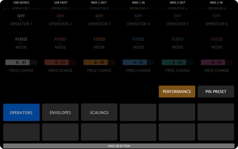
The currently selected page is highlighted. Page names are positioned on screen to align visually with the knobs, making it intuitive to select a page by either tapping the on-screen page button or touching the corresponding knob.
Note: The ability to select pages using knob touch can be disabled in the controller’s settings. When disabled, only touch gestures or hardware buttons will change pages.
Empty (unnamed) page buttons represent unused pages and cannot be accessed.
There are two special buttons on the Page selection: The Performance and the Pin Preset.
Performance button - opens the Performace page if the currently active preset includes one. The Performance page allows you to control a custom selection of parameters across multiple preset pages — all in one place. It’s ideal for performance setups, macro controls, and live tweaks.
Pin Preset button - lets you pin or unpin the current preset. When pinned, the preset remains active and continues processing MIDI even after you switch to a different preset. A pin icon appears in the top-right corner of the preset's button to indicate that it’s pinned. When preset is pinned, the button is highlighted (shown in blue).
The hardware buttons on Page selection
While the PAGE SELECTION window is open, the six hardware buttons do something other than what they normally do:
| Button | While PAGE SELECTION is open |
|---|---|
[LEFT-TOP] | reboots the controller |
[LEFT-MIDDLE] | nothing |
[LEFT-BOTTOM] | puts the controller to sleep |
[RIGHT-TOP] | opens the USB Host window |
[RIGHT-MIDDLE] | opens preset selection |
[RIGHT-BOTTOM] | closes the window |
The button combinations described elsewhere in this manual are made of these two steps. [RIGHT-BOTTOM] is what opens the window in the factory button layout, so holding it and then pressing [LEFT-TOP] reboots the controller, and holding it and then pressing [LEFT-BOTTOM] puts it to sleep.
When you open the window by holding [RIGHT-BOTTOM], releasing the button closes the window again, but only if you browsed the pages while it was held. This is what lets you glance at the pages and return to where you were.
Devices
The Devices section of the main menu displays how the MIDI devices in the current preset are configured in terms of MIDI ports and channels. Users can use this screen to adjust the MIDI settings of each device to fit their specific setup.
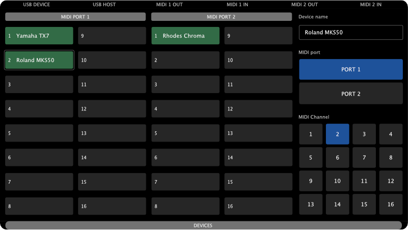
Changes made here do not modify the original preset. Instead, they are saved separately as device overrides when you close the Devices window. This allows users to customize the MIDI port, channel, and interfaces of each device without altering the preset itself — ideal for adapting shared or downloaded presets to different hardware setups.
The screen is divided into three parts:
MIDI PORT 1- a list of the 16 MIDI channels of Port 1MIDI PORT 2- a list of the 16 MIDI channels of Port 2- A form to adjust the settings of the currently selected device
Configured devices are shown in green. The number in front of each entry indicates the MIDI channel. The currently selected device, i.e. the one whose details are shown in the form is highlighted with a light gray outline.
Let’s review the example below:
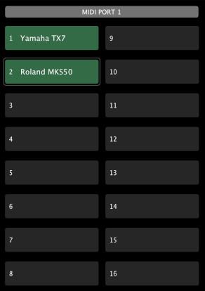
This list shows all MIDI devices on MIDI Port 1, whether they are reached through <MIDI IO>, <USB DEVICE>, or <USB HOST>. The Yamaha TX7 is listening on MIDI channel 1, and the Roland MKS50 on channel 2. Other channels are unused.
The Roland MKS50 is currently selected, so its details are displayed in the form:
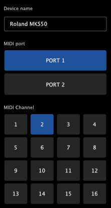
To select another device, simply tap its entry. Note that you cannot select unused channels. The form shows the device name and these settings:
- MIDI Interfaces - the
MIDI IO,USB DEVICE, andUSB HOSTbuttons choose which interfaces the device is wired to. Its messages are sent, and its messages are received, only through the highlighted interfaces. Tap a button to turn an interface on or off; at least one interface stays on. - MIDI Port - the port the device is on.
- MIDI Channel - the channel the device is on.
Running status is not on the form. It is set for the device in the preset, and overrides do not change it.
If the selected port and channel are already used by another device, the controller swaps the two devices: the other device takes the port and channel the selected device had. Two details are worth knowing:
- A device is in the way whichever interfaces it uses. Only the port and the channel are compared, so a device on
USB HOSTis swapped out by a device you move onto its port and channel overMIDI IO. - The device that is moved out of the way keeps its own interfaces. Only the device you are editing gets the interfaces you chose.
Snapshots
Snapshots allow you to save and recall the full state of all controls in a preset — effectively capturing a moment in time that you can return to at any point. This is especially useful for performance, sound design, and working with complex setups.
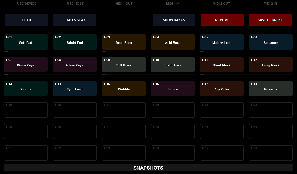
Each preset can contain up to 12 banks, with 36 snapshots per bank, giving you a total of 432 snapshots per preset. The snapshot banks selection is revealed by tapping the [SHOW BANKS] button.
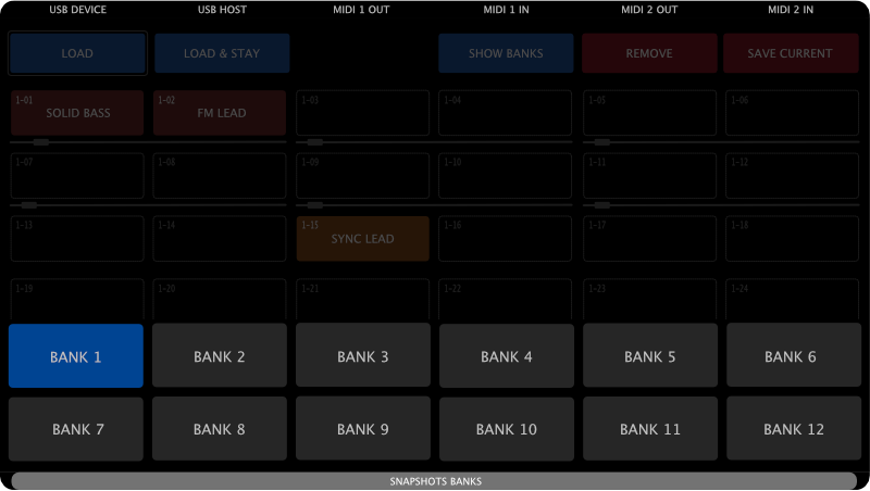
Banks are called Bank 1 to Bank 12 unless you give them names of your own. A bank name may be up to 20 characters long and is stored per preset projectId, alongside the snapshots themselves. Bank names are set from a host application over the SysEx API, not on the controller itself; clearing a name puts the bank back to its Bank n default.
Snapshots are stored per preset projectId, meaning that if the same preset is loaded into multiple slots on your Electra One, those instances will share the same snapshots. If you want each instance to have its own independent set of snapshots, create a copy of the preset (which will get a new projectId) and upload it to the other slot.
When you save a snapshot, the current values of all controls in the preset will be stored in it. There is one exception, controls with the Message type set to None (used to create display-only or virtual controls that are intentionally excluded from snapshot saving)
The Snapshots screen is divided into two main parts: action buttons and a grid of snapshot slots.
The Action buttons
The action buttons allow you to select the operation you want to perform on the snapshot slots. There is one exception: the [SHOW BANKS] button simply opens the bank selection screen.

The currently selected action is highlighted with a light gray outline. In the example above, the Snapshots screen is in LOAD mode—meaning that tapping any snapshot slot will immediately load that snapshot. Tapping a different action button will change the mode accordingly.
Available actions:
[LOAD]- snapshot load mode. A snapshot will be loaded and the snapshots screen closed.[LOAD & STAY]- persistent snapshot load mode. The snapshots screen will not be closed after the snapshot is loaded.[SHOW BANKS]- shows the selection of snapshot banks.[REMOVE]- snapshot remove mode. tapping on snapshot slots will clear them.[SAVE CURRENT]- save snapshot mode. tapping on a snapshot slot will save current values there.
The Snapshots grid
The Snapshots grid displays the available snapshot slots where you can save, load, or remove snapshots. Each bank contains 36 slots, arranged in a 6×6 grid.
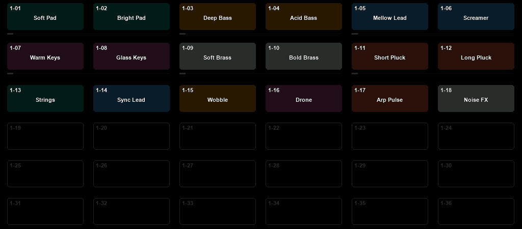
The actions performed on the slots depend on the selected mode, which is set using the action buttons described above.
Each snapshot slot includes information about its bank number and position within the bank. For example:
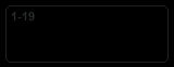
This represents an empty snapshot slot. The 1-19 label in the top-left corner indicates that this is Bank 1, Slot 19.
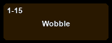
This represents a used snapshot slot. The 1-15 label indicates Bank 1, Slot 15. Used snapshot slots display a name and a color, making it easier to identify them.
When a new snapshot is saved, it is automatically assigned a default name and color. You can later rename and recolor your snapshots using the Electra One web editor, allowing for better organization and easier recall.
Morphing slots
The top two rows of snapshot slots offer an advanced feature designed for sound design and performance: snapshot morphing.

Under each pair of snapshot slots, you'll see a slider. There are six sliders in total, and each one is linked to two knobs on the controller.
When you touch any of the knobs, the corresponding slider is highlighted and will become armed to snapshot morphing or randomization.
Morphing
The left knob in the pair is used for morphing, ie. a smooth transition (morph) between the two snapshots linked to that slider.
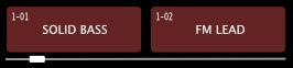
- When the slider is all the way to the left, the values from the left snapshot are used.
- When it is all the way to the right, the values from the right snapshot are used.
- Any position in between blends the values from both snapshots, creating an interpolated (crossfaded) version of the sound.
This feature makes it easy to experiment with new sounds by smoothly transitioning between saved configurations, giving you precise control over your sound in real time.
By using two snapshots in the morphing process, you gain additional control over which parameters are affected and how strongly the transition influences the sound.
Randomization
The right knob in each snapshot pair is used to apply randomization to the control values. While it works similarly to morphing, randomization generates new, random values within a defined range rather than blending existing ones.
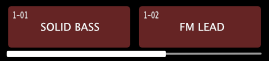
The range of randomization is determined by the values in the left and right snapshot slots. For each parameter, the difference between the two snapshots defines the maximum allowed randomization range.
The slider beneath the pair controls the amount of randomization applied:
- With the slider fully left, no randomization is applied.
- Moving the slider towards the right increases the intensity of randomization.
- At the far right, values are randomized across the full range between the two snapshots.
This allows for controlled sound variation while staying within predictable limits defined by the snapshot pair.
Saving morphed and randomized snapshots
Newly created sounds can be saved to snapshot slots by switching to [SAVE CURRENT] mode and tapping the desired snapshot slot.
The snapshot tool bar
The snapshot tool bar lets you build a series of variations of a sound without opening the Snapshots window again for each one.
Switch to [SAVE CURRENT] mode and touch and hold a free slot. The current values are saved into that slot, the window closes, and the tool bar appears in the row above the controls, where the page buttons go. The Status bar is hidden while the tool bar is on the screen.
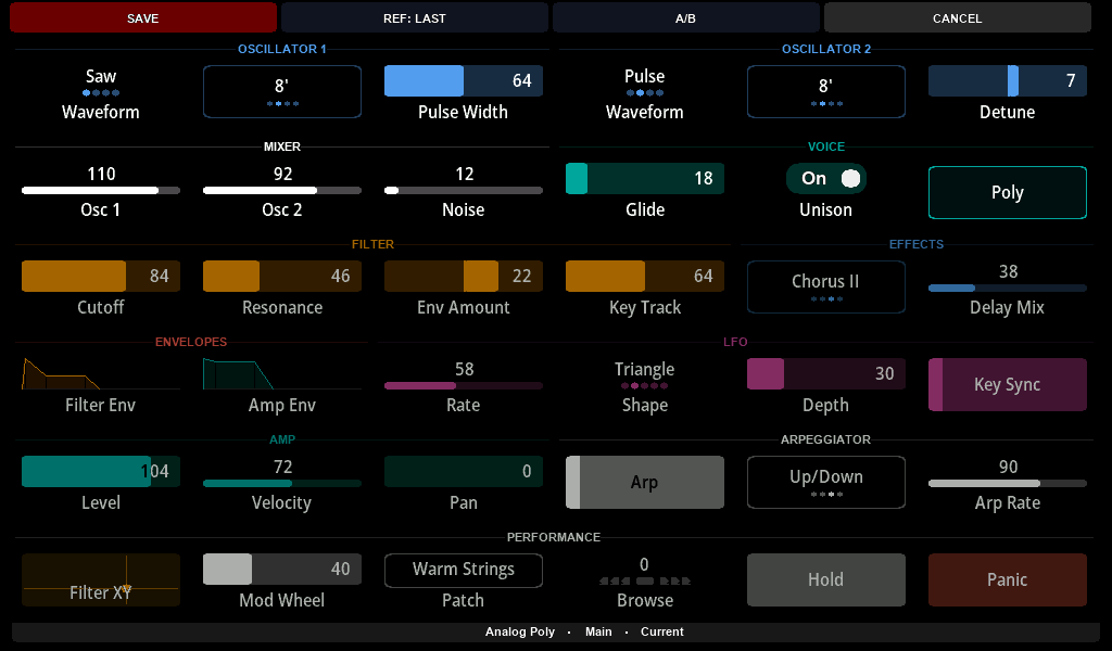
The tool bar has four buttons:
SAVE- saves the current values into the next slot of the bank. When the last slot of the bank has been used, the button readsRETAKE; tapping it starts again from the first slot after the one you held.REF: LAST/REF: FIRST- chooses whatA/Bplays: the variation you saved last, or the snapshot you started from.A/B- switches between the reference and the values you are working on. Tap it to hear the reference, and again to return to your own values, exactly as you left them. If you change a value while you hear the reference, that becomes your current sound, and the next tap keeps it.CANCEL- closes the tool bar. Everything you saved stays in its slot.
A button lights up while you touch it. The Bottom bar shows what you are hearing after the preset and page names - A0 First or D3 Last while A/B plays the reference, Current otherwise - and confirms each save for about two seconds, for example Snapshot D0 saved.
The tool bar closes when you load another preset, and when you open the Snapshots window again; the window then opens below the Status bar as usual. What it is for, and a worked example, is described in Quick variations with the Snapshot tool bar.
Captures
Captures record MIDI and play it back. A capture is a Standard MIDI file, so one capture can hold a patch dump, a bass line or a whole take — notes, controller movements, SysEx, and the tempo and time signature they were played at. A capture can hold about 64 KB of MIDI data, up to 16384 events. What captures are and what they are used for is described in Captures; this section describes the CAPTURES window on the mk2.
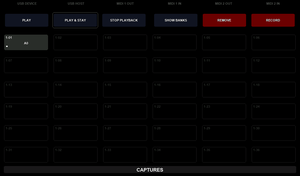
Each preset has access to 12 banks, with 36 capture slots per bank, giving you a total of 432 capture slots.
Besides a name and a colour, each capture has playback settings of its own: the interface and port it plays to, whether it loops, whether it follows MIDI clock, and a root note used for transposing. These are set in the Electra One app, not on the controller.
Capture banks are named the same way snapshot banks are: Bank 1 to Bank 12 by default, or a name of up to 20 characters set from a host application over the SysEx API. Snapshot banks and capture banks are named independently of one another.
Captures are stored per preset project ID, meaning that if the same preset is loaded into multiple slots on your Electra One, those instances will share the same captures. If you want each instance to have its own independent set of captures, create a copy of the preset (which will get a new project ID) and upload it to the other slot.
Action Buttons
The action buttons at the top of the Captures screen define what happens when you tap a capture slot. There are six of them, in this order:

Available actions:
[PLAY]– Plays the capture in the slot you tap and closes the window.[PLAY & STAY]– Plays the capture and keeps the window open, so you can start several captures one after another.[STOP PLAYBACK]– Stops every capture that is playing. This button is shown only while something is playing.[SHOW BANKS]– Opens the capture bank selection screen.[REMOVE]– Clears the slot you tap.[RECORD]– Records into the slot you tap.
The currently active action is highlighted with a light gray outline. The window opens in [PLAY] mode, or in [RECORD] mode while a slot of the bank shown is armed for recording. After selecting an action, tapping a slot will perform the corresponding operation.
Captures Grid
The Captures grid displays the available capture slots where you can record, play, or remove captures. Each bank contains 36 slots, arranged in a 6×6 grid.
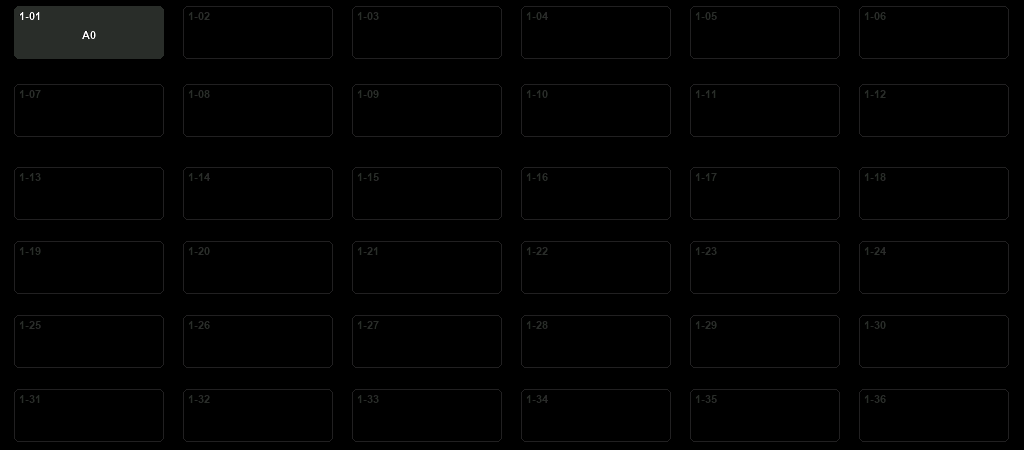
The actions performed on the slots depend on the selected mode, which is set using the action buttons described above.
Each capture slot includes information about its bank number and position within the bank. For example:
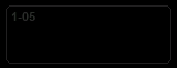
This represents an empty capture slot. The 1-05 label in the top-left corner indicates that this is Bank 1, Slot 5.
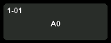
This represents a used capture slot. The 1-01 label indicates Bank 1, Slot 1. Used capture slots display a name and a color, making it easier to identify them.
A slot also shows two things while you work with it:
- a loop symbol in the top-right corner, when the capture is set to repeat,
- a white bar under the name while the capture is playing, showing how far it has played.
When a new capture is saved, it is automatically assigned a default name and color. You can later rename and recolor your capture using the Electra One web editor, allowing for better organization and easier recall.
Playing a Capture
Tap [PLAY] and then a capture slot: the capture plays and the window closes. To start several captures, tap [PLAY & STAY] first — the window then stays open, so you can tap one slot after another.
Up to eight captures can play at the same time. A capture started while others are playing waits for the next bar line of the capture that started first, so they stay in time with each other.
Tapping the slot of a capture that is playing stops it if it loops, and starts it again from the beginning if it does not. [STOP PLAYBACK] stops everything, including captures in banks the window is not showing.
The messages a capture plays also reach the preset, so the controls move with a recorded knob sweep, and a recorded SysEx patch dump updates them through the device's patch rules. See Playback for the details, and for the ways a capture can be started from another MIDI device or from Lua.
Recording a new Capture
Recording a new Capture involves the following steps:
- Select the record mode by tapping the
[RECORD]button. It will be highlighted with a light gray outline to indicate that recording mode is active. - Choose a capture slot by tapping it. The selected slot will be highlighted with a yellow outline, indicating it is armed and waiting.

- Play. The recording starts with the first MIDI message that arrives. MIDI clock alone does not start it.
- Tap the same slot again, or tap
[RECORD], to stop. The capture is saved into the slot and given a default name and color.
Tapping a different slot while a recording runs saves that recording first and then arms the new slot. A recording saved into a slot that already holds a capture replaces it.
You can close the window while a recording runs — swipe down, or press any hardware button — and the recording goes on. When you open the window again it is in [RECORD] mode with the slot still armed, and tapping the slot stops the recording.
A recording stops by itself only when the memory is full, at about 64 KB of MIDI data. It is saved at that point.
If nothing is received, or if you change your mind, you can disarm the slot by simply tapping it again.
The capture tool bar
The capture tool bar lets you record while the preset page is on the screen, so you can record the knob moves you make.
Tap [RECORD], then touch and hold a capture slot. The window closes, and the tool bar appears in the row above the controls, where the page buttons go. The Status bar is hidden while the tool bar is on the screen. Nothing is recorded yet.
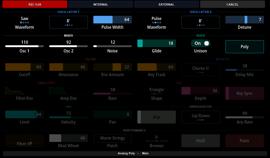
The tool bar has four buttons:
RECORD- starts the take at once. While it records, the button is bright red and shows the elapsed time, such asREC 0:05. Tap it again to stop: the capture is saved, the tool bar closes, and the Bottom bar showsCapture A0 saved, with the name of the new capture, for about two seconds.INTERNAL- a toggle. When on, the messages the controller sends itself are recorded: a knob you turn, a button you press, the MIDI a Lua script sends.EXTERNAL- a toggle. When on, the messages that arrive at the controller are recorded: from the MIDI sockets, from USB instruments and from the computer.CANCEL- discards the take and closes the tool bar.
A button lights up while you touch it.
With the tool bar the recording starts when you tap RECORD, not with the first message that arrives. See Recording for what a capture records and what it leaves out.
Patch request
If the preset includes instructions to request patch data from a device, tapping the [PATCH REQUEST] button will send the necessary request messages. If the preset includes the patch dump parsing instructions, when the connected device responds with a patch dump via MIDI, the Electra One controller will automatically update the control values to reflect the received patch settings.
If the preset includes instructions to request and parse patch data from a device, tapping the [PATCH REQUEST] button will send the necessary request messages. When the connected device responds with a patch dump via MIDI, and if the preset includes parsing instructions, the Electra One controller will automatically update the control values to reflect the received patch settings.
Router
Electra One has a low-latency internal MIDI router that forwards MIDI messages between its interfaces:
<USB DEVICE>- The Electra One USB interface as seen by your computer.<USB HOST>- MIDI devices connected to Electra One’s USB host port.<MIDI IO>- MIDI devices connected to Electra One’s 5-pin DIN MIDI connectors.
Each interface provides two MIDI ports: Port 1 and Port 2. The router can also pass messages to two of Electra One's own services, the Remote Knobs and MIDI Control. How the router works, and how a preset can add a router script of its own, is explained in the Router chapter.
A preset's own router script does not run until you allow it. The switch is the Enable preset router scripts checkbox in the Router section of the Electra One app; there is nothing for it on the Router configuration screen. It is off by default, because a router script runs above the display and the user interface, so turning it on is a deliberate act rather than something a file in a preset slot does by itself.
Router Configuration Screen
The router is managed on the Router configuration screen:
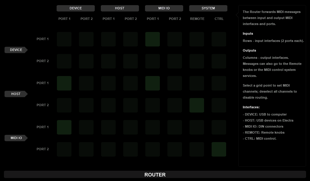
The screen is organized as a grid of 6 rows and 8 columns:
- Rows represent MIDI sources: Port 1 and Port 2 of
DEVICE,HOSTandMIDI IO. - The first six columns represent MIDI destinations: Port 1 and Port 2 of the same three interfaces.
- The last two columns,
REMOTEandCTRL, pass messages to the Remote Knobs and to MIDI Control.
Each square in the grid is a possible route from a source to a destination. A lit square is an active route. When no square is selected, the sidebar on the right shows a short help.
Enabling and Disabling Routes
- Tap a square to select it. It is outlined, lines lead from it to its source row and its destination column, and the sidebar shows the route's settings.
- Tick All channels in the sidebar to turn the route on. Untick it to turn the route off.
- For the
REMOTEandCTRLcolumns, you can pick Individual channels instead, so that only messages on those channels go to the Remote Knobs or MIDI Control. - Tap the selected square again to close its settings.
Changes are saved when you close the screen.
A route to REMOTE or CTRL does not forward anything. It tells the Remote Knobs or MIDI Control which messages to listen to. Messages they take are not passed to the preset, but the other routes from the same source still forward them.
A simple MIDI Thru on <MIDI IO> Port 1 is a single route: the square in the MIDI IO Port 1 row and the MIDI IO PORT 1 column. Any MIDI data received on the MIDI 1 IN socket is then sent out of MIDI 1 OUT.
To see incoming MIDI while you set up routes, watch the status bar at the top of the screen, which lights up for every interface that receives messages.
Forwarding to <MIDI IO>
The MIDI sockets are much slower than USB: they carry roughly 3,000 bytes per second, while a computer or a USB controller can send far more. When you route a busy USB source to <MIDI IO>, for example a DAW sending dense automation, the socket may not keep up. Forward only what the instruments on the sockets need. A router script can filter the rest out, as described in the Router chapter.
The controller's own MIDI clock
Besides forwarding the MIDI clock of another device, Electra One can generate a clock of its own and send it to the interfaces and ports you choose. This is useful when nothing else in your setup keeps time.
There is one clock for the whole controller, and it is started from a preset's Lua script rather than from a screen. The tempo can be set between 20 and 400 BPM; it is 120 BPM until a script sets it. The functions are transport.setTempo, transport.enableClock, transport.startClock and transport.setClockOutputs, described in the Preset Lua Extension.
Two things follow from there being only one clock:
- The clock belongs to the preset that started it. When that preset goes — you switch away from it without pinning it, unpin it, or reload it — the clock stops. A Stop message is sent if the transport was playing.
- The clock does not run while a MIDI clock is arriving on any input. Electra One follows that clock instead, and carries on with its own once the incoming clock has been silent long enough to count as gone.
USB Host
As you’ve learned already, Electra One functions as a USB Host, allowing you to connect up to two USB MIDI devices at the same time.
- One device can be connected directly to Electra's USB Host port.
- To connect two devices, a standard USB hub must be used.
Device Detection and Port Assignment
When a USB MIDI device, such as a controller or synthesizer, is connected, Electra One automatically detects it and displays its available ports on the USB HOST DEVICES screen.
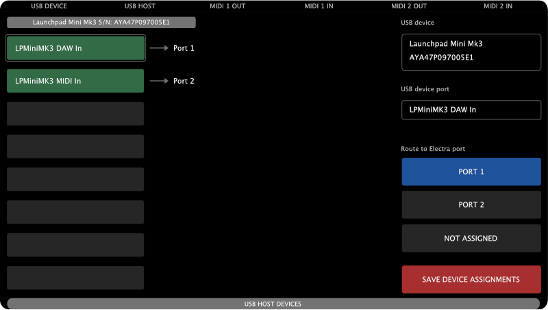
This screen allows you to assign each detected MIDI device port to one of Electra One’s internal ports:
- Port 1
- Port 2
- CTRL
You can also choose to leave a port unassigned if you don’t want Electra to use it.
When nothing is connected, the screen reads No USB MIDI Devices connected and You can connect up to two USB MIDI devices using a USB hub.
Each connected USB MIDI device is displayed with its name and serial number at the top, along with a list of all its available ports and their current assignments to Electra’s internal ports.
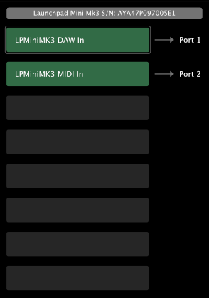
The example above shows a Novation Launchpad connected to Electra One, with its LPMiniMK3 DAW In port assigned to Electra’s internal Port 1, and its LPMiniMK3 MIDI In port assigned to Port 2.
When two devices are connected, two columns (one for each device) will be displayed.
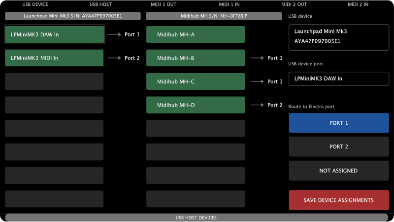
The second device is a Blokas Midihub:
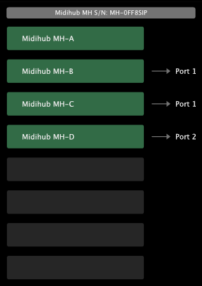
- port MH-A is not assigned
- port MH-B is assigned to Port 1
- port MH-C is assigned to Port 1
- port MH-D is assigned to Port 2
To assign or unassign a port, tap the MIDI device's port (highlighted in green). The selected port will then be outlined in light gray. The right sidebar will update to display relevant information and available actions for that port.
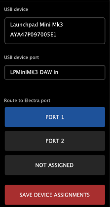
The sidebar shows the name and serial number of the MIDI device under the label USB device, the selected port under USB device port, and four buttons under Route to Electra port:
[PORT 1]and[PORT 2]hand the device's messages to the preset, as if they had arrived on that port of any other interface.[CTRL]hands them to Electra One itself, as if they had come from the computer's CTRL port: notes trigger captures, control changes morph snapshots, and program changes switch presets. This is how a pad controller plugged into the USB Host port can drive the controller directly.[NOT ASSIGNED]cancels the assignment, so Electra One ignores the port.
It also includes a button to save all device port assignments (see below).
Saving and Recalling Assignments
Tapping a port button takes effect straight away on the device that is connected. To make the assignment survive a reconnect or a restart, save it: press and hold the [SAVE DEVICE ASSIGNMENTS] button until it fills. Letting go early saves nothing. The next time the device is connected, Electra One will automatically apply the saved settings.
If you connect multiple USB MIDI devices at different times and save their port assignments, Electra One will remember the configuration for each device individually.
Saved assignments are matched against the device's product name. The match ignores capitalisation and succeeds when the saved name appears anywhere in the device's name, and only the first saved entry that matches a device is used. A device that matches nothing uses Port 1.
This makes it easy to maintain a consistent setup across sessions—whether you're working in the studio or performing live.
Settings
The Settings is used to configure your Electra One controller. Since it contains a wide range of options, it is covered in detail in its own dedicated Settings chapter.
Reboot
The REBOOT button restarts the Electra One controller.
REBOOT is a hold-to-confirm button. Press and hold it until it fills; releasing it early does nothing, so the controller cannot be restarted by a stray touch.
In addition to performing a standard reboot, this button can be used in combination with key holds to trigger special startup modes.
While holding the on-screen REBOOT button, you can hold one of the following hardware buttons to modify the startup behavior. Note: You must continue holding the hardware button until the startup animation finishes for the selected mode to take effect.
- Hold
[LEFT-TOP]while holding REBOOT → The controller will start without loading any preset. - Hold
[RIGHT-BOTTOM]while holding REBOOT → The controller will enter bootloader mode for firmware updates, recovery, and the SD card file management.
These combinations are useful for advanced tasks such as troubleshooting and maintenance.
Starting without a preset
Starting with [LEFT-TOP] held is what you use when a preset stops the controller from working — for example when its Lua script blocks it. The controller starts with an empty preset, and it does not start the pinned presets either, which matters when a pinned preset is the one causing the trouble.
Your presets stay on the controller. Replace or delete the preset that caused the problem in the Electra One app, then restart normally. If you restart without doing so, the same preset and the saved pins are loaded again.
[LEFT-TOP] is read at every start, so this works at power-on too: unplug the controller, hold [LEFT-TOP], plug it in, and keep the button held until the display shows a page.
Sleep
The SLEEP button activates Sleep Mode on the controller.
SLEEP is a hold-to-confirm button, like REBOOT. Press and hold it until it fills; releasing it early does nothing.
The controller then enters a low-power state with the display turned off. It also prepares for safe power disconnection by completing any pending file operations and closing its internal database.
While in Sleep Mode, it is safe to disconnect the USB cable, or you can simply leave the controller in Sleep Mode while still connected.
To wake the controller from Sleep Mode, press any hardware button.